 |  |
Projects:
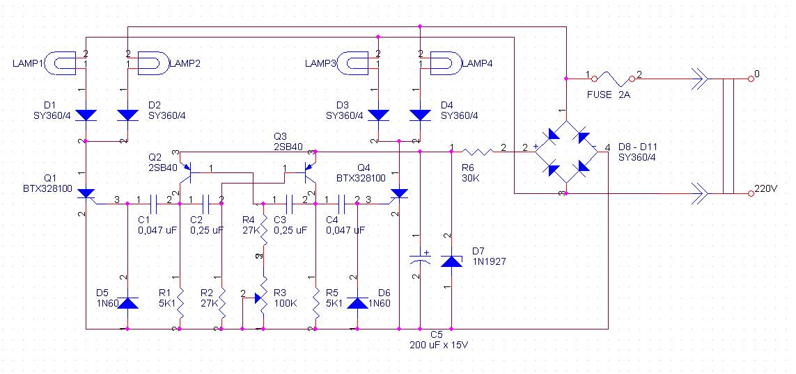
Light effect "Running line"
*****ATTENTION! HIGH VOLTAGE IS IN USE*****
This simple light effects I made when I started interest in electronics. This schematic creates light effect so called "running line" and couple of other effects. LP1 -LP4 are filament light bulbs supplied with 220V. R6 powershould be at least 2 W. Diodes D1 - D4, D8 - D11 might be Russian Д226Б. Diodes D5 and D6 - Russian Д9Б. Zenner D7 - Russian Д814A. Transistors Q2 and Q3 might be changed with Russian MП42Б, thyristors Q1 and Q4 - changed with Russian KУ202N.
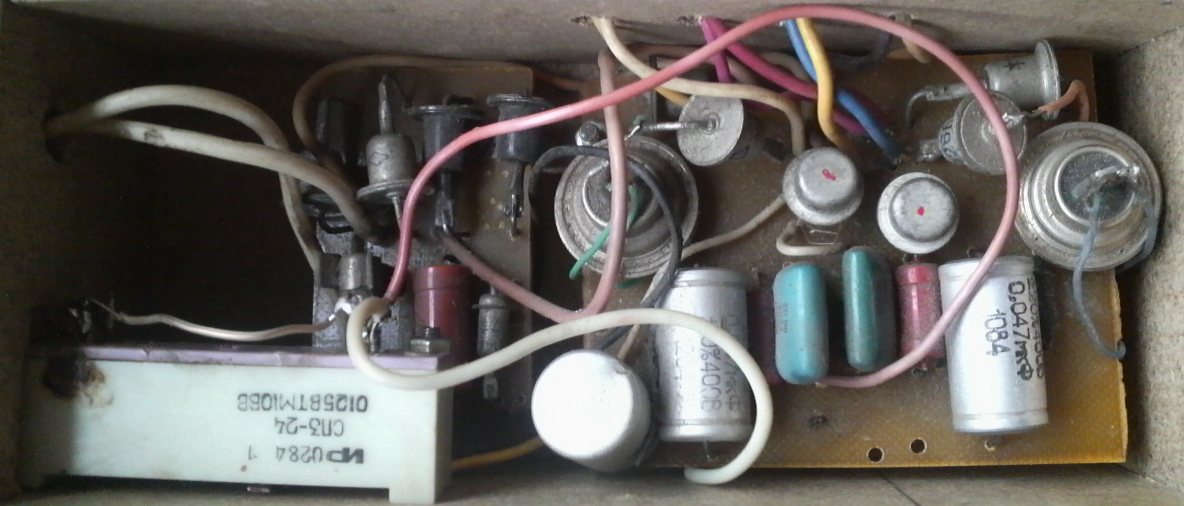
How it looks... | This ir the beginner's assembly :) |
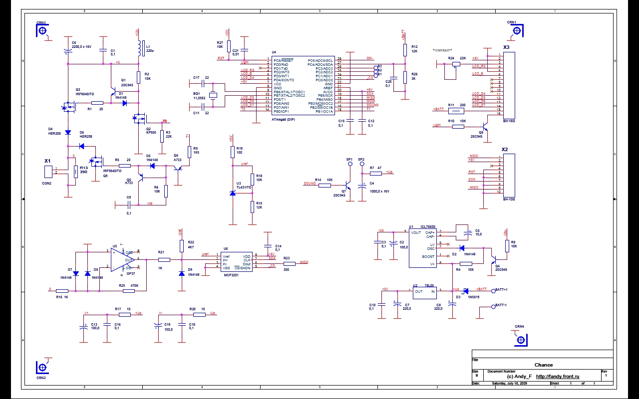
Metal detector "Chance"
I interested in the opportunity to make a metal detector (hereinafter - MD) accidentally. After some time of searching online, I decided to try to make pulse MD “Chance”, designed by Russian constructor Andy_F. Author described the construction and parameters of his prototype, in his webpage http://fandy.vov.ru/Chance.htm. Of course, everything is described in the Russian language. Since not all enthusiasts of electronics understand Russian, I'll try to describe in detail all the construction process of my prototype.
MD has liquid crystal display to display all indications. Also it has a sound signal. The MD should have the discrimination, what is to say that It should separate the type of metal. |
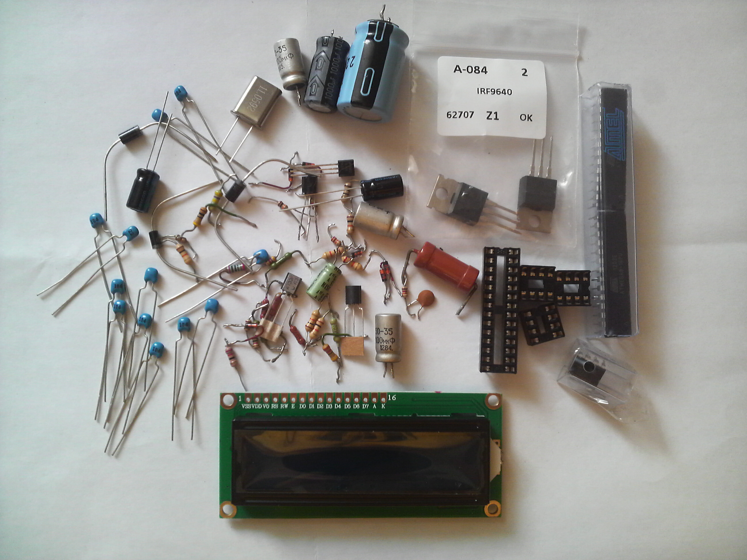
So, first of all it is necessary to have the circuit of MD. It can be
downloaded from here. You will find the circuit, the assembly, the list of
parts, the file with Atmega MCU program in the downloaded folder.
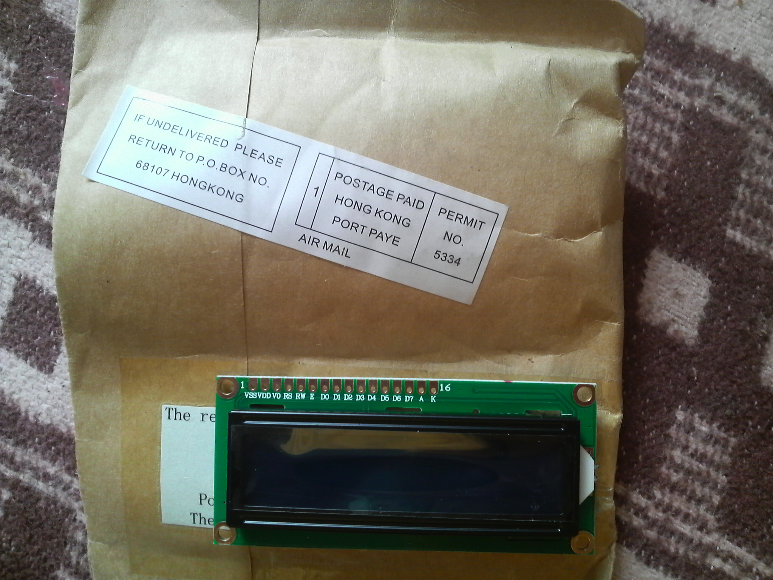
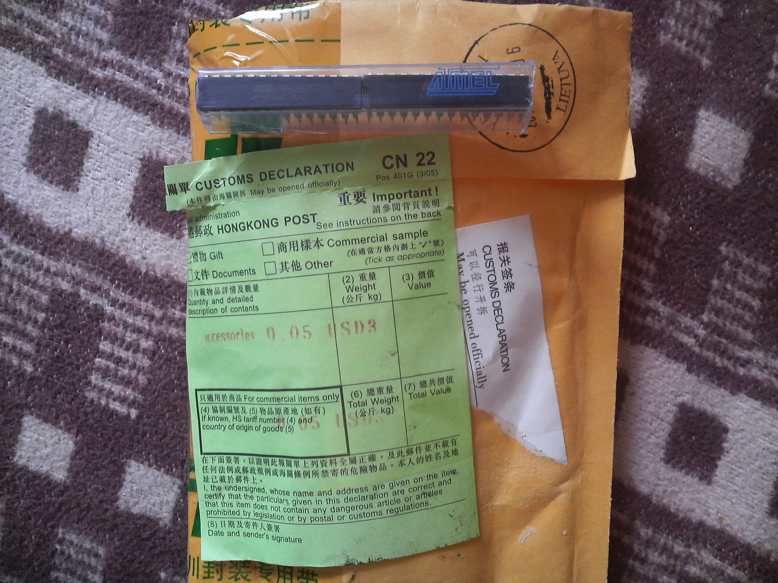
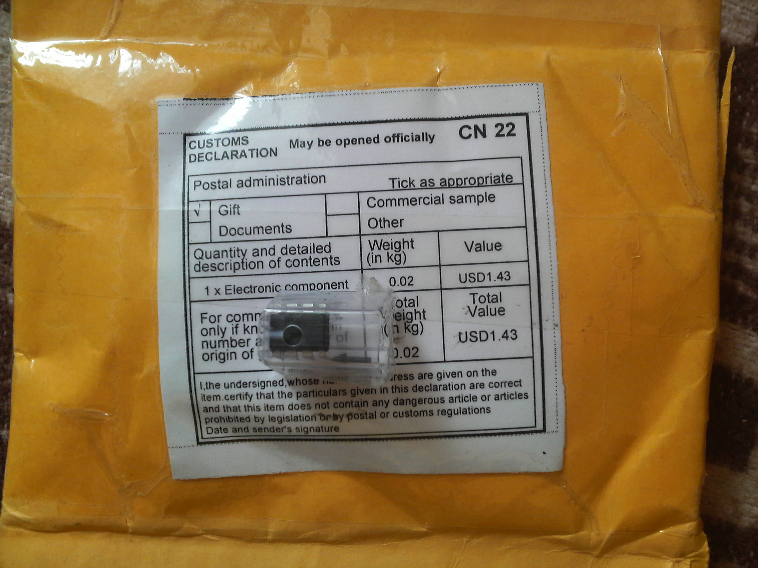
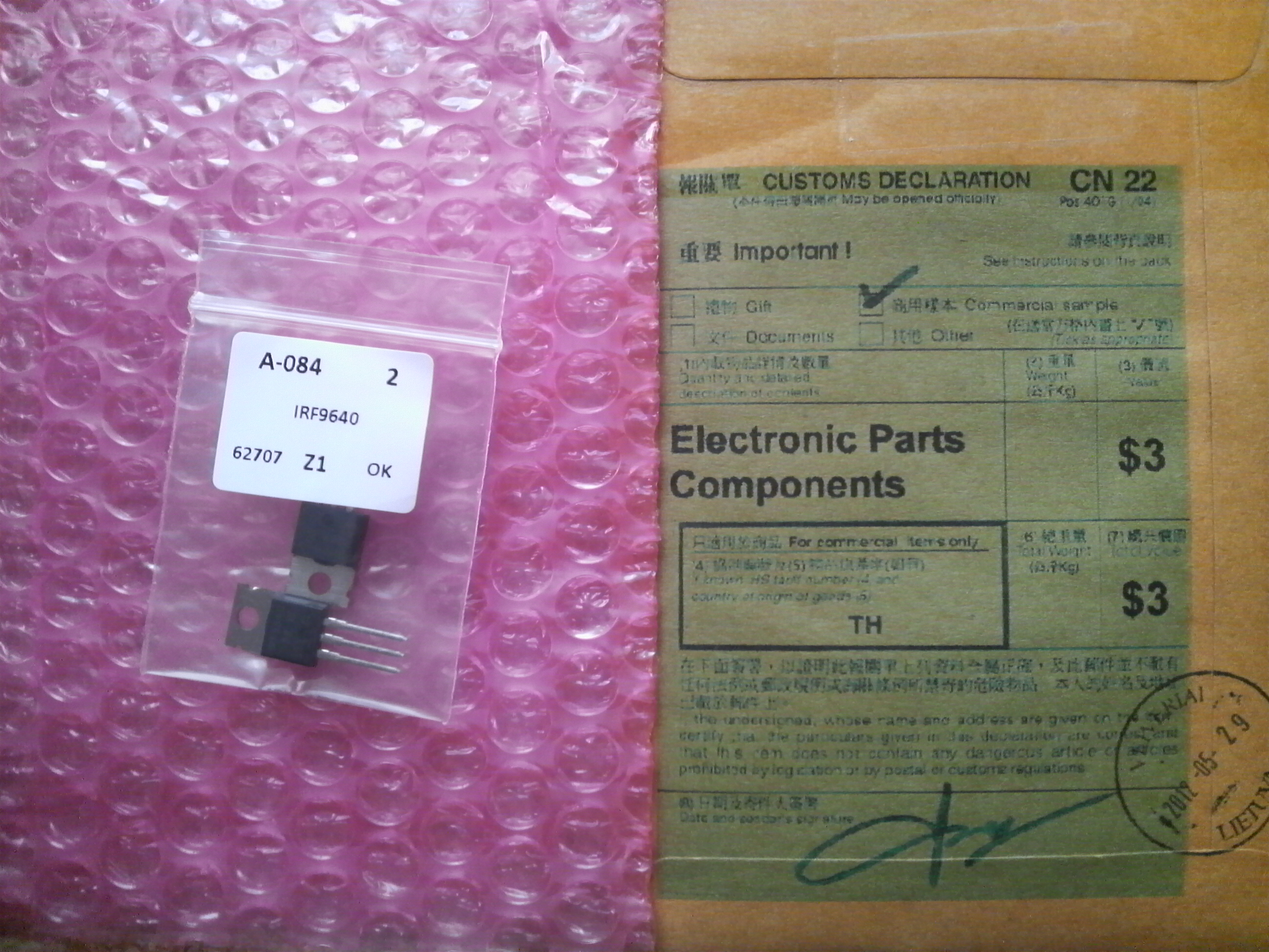
All parts can be found or ordered in Lithuania. I've bought some parts on E-bay,
as there is a significant price difference compared to the Lithuanian prices. I
have no to rush somewhere, so I could afford to wait and save some money. All
the parts ordered on E-Bay arrived within a good two weeks without any problems
and additional costs in Lithuania.
Once we have all the parts, we can try to make double-sided PCB in to which we will solder all parts. The PCB I made using a widely known and often used technique when using laser printer on the "coated" paper is printed circuit image. This image then is transferred onto a board using simple iron.
Will be continued...
Vinyl corrector with J-Fets
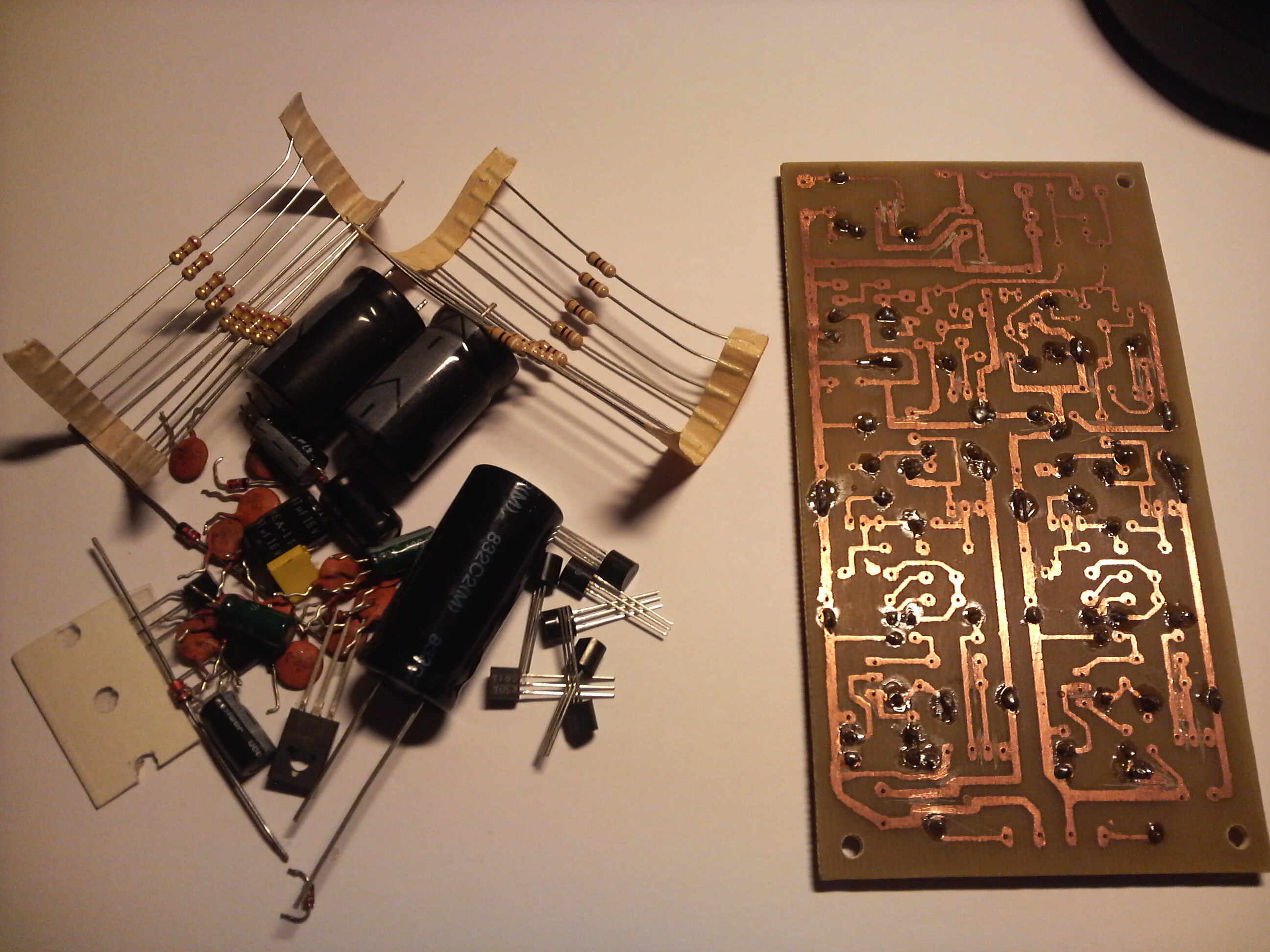
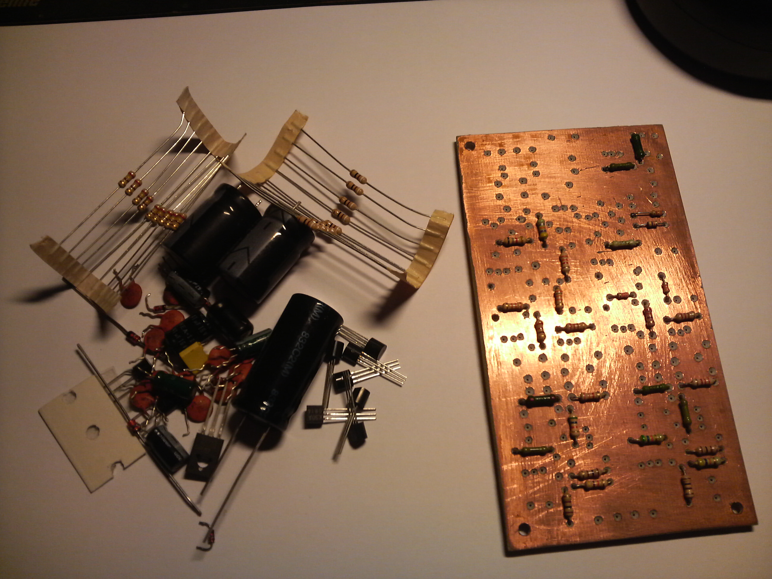
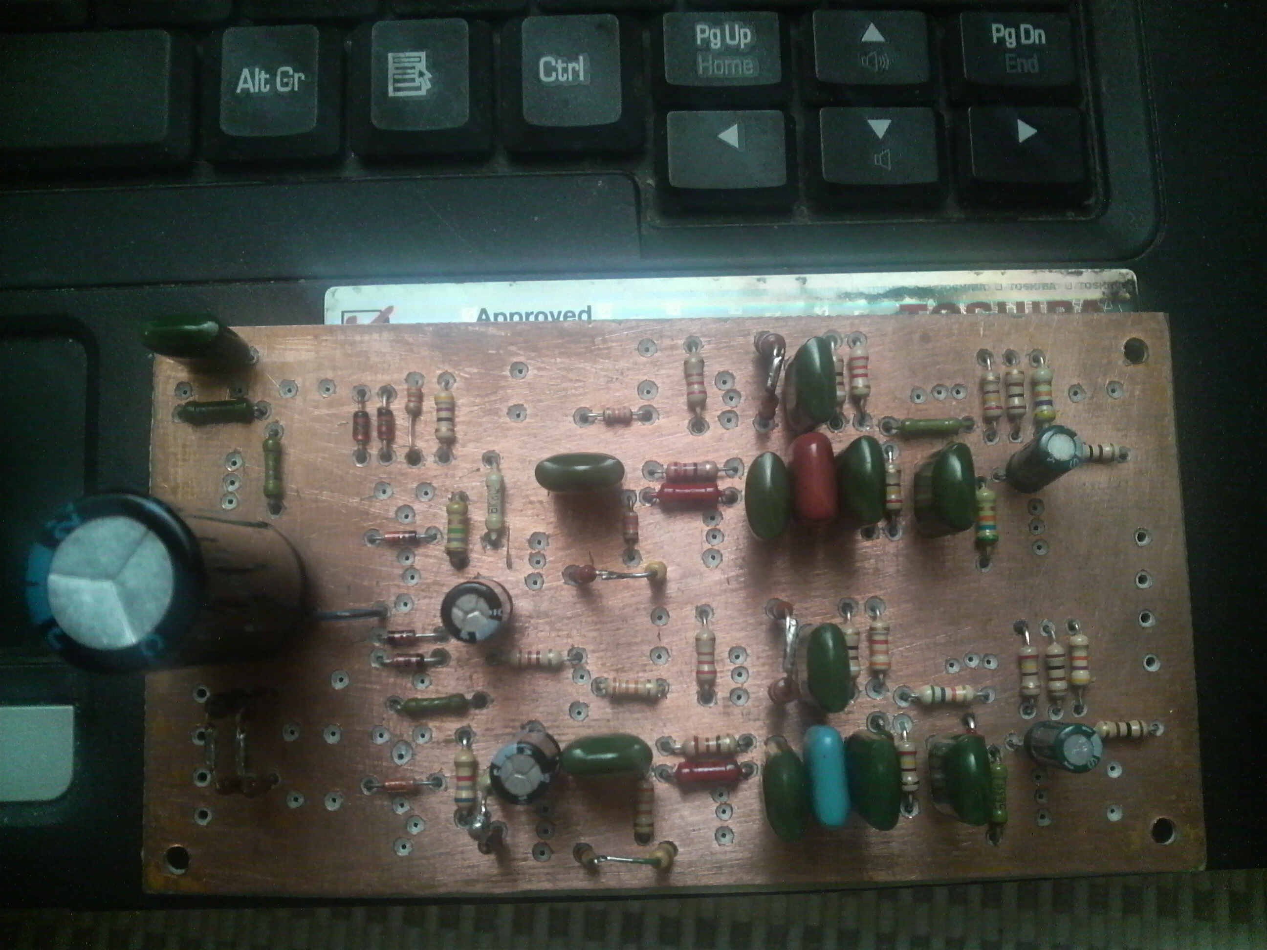
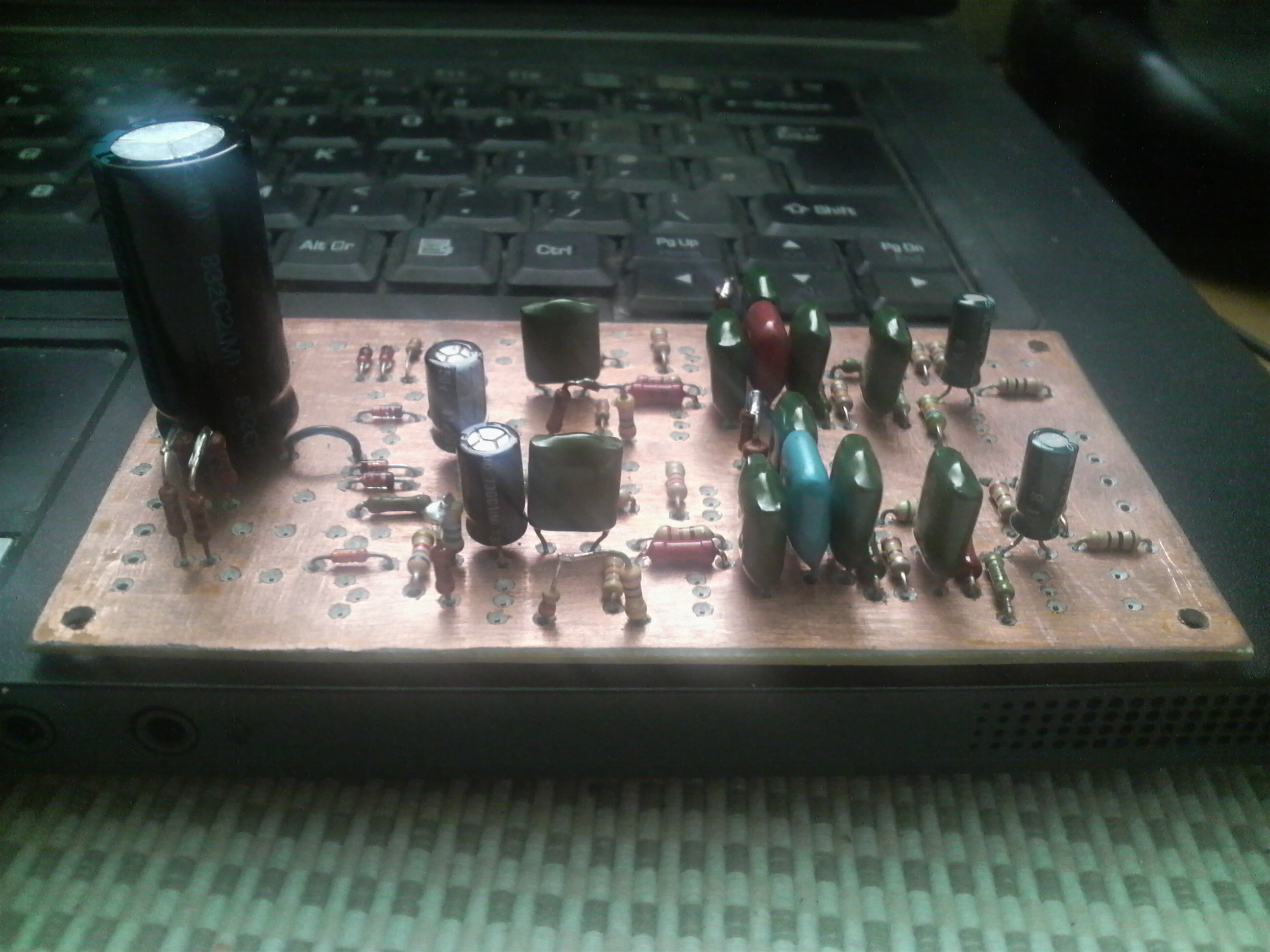
Some time ago I had an idea to buy any turntable to listen vinyl records sometimes. Well, I bought some kind of for first acquaintance. However, I couldn‘t connect the turntable to my amplifier (it has no a “phono connector”). So, it was necessary to assemble so called „vinyl corrector“ (“phono corrector”). After some searching I decided to stay on this project: http://audio.ring.lt/riaa/riaa.html?temp-new-window-replacement=true. I didn’t change anything in the circuit or pcb. I was eager to assemble some kind of vacuum tubed vinyl corrector, but I decided experiments with vacuum tubes to reschedule, simply because no projects with tubes have been done yet. All components used the same as in schematic diagram.
The circuit of corrector’s power supply filter I found at the same website too. All components used the same as showed in the circuit. Several pictures of vinyl corector in building process |
Circuit ciagram of vinyl corrector |

Several pictures of power supply filter pcb | Circuit ciagram of power supply filter. I used upper part of it.
|
Corrector was successfully finished and works good. Besides, I need better turntable, I think :)
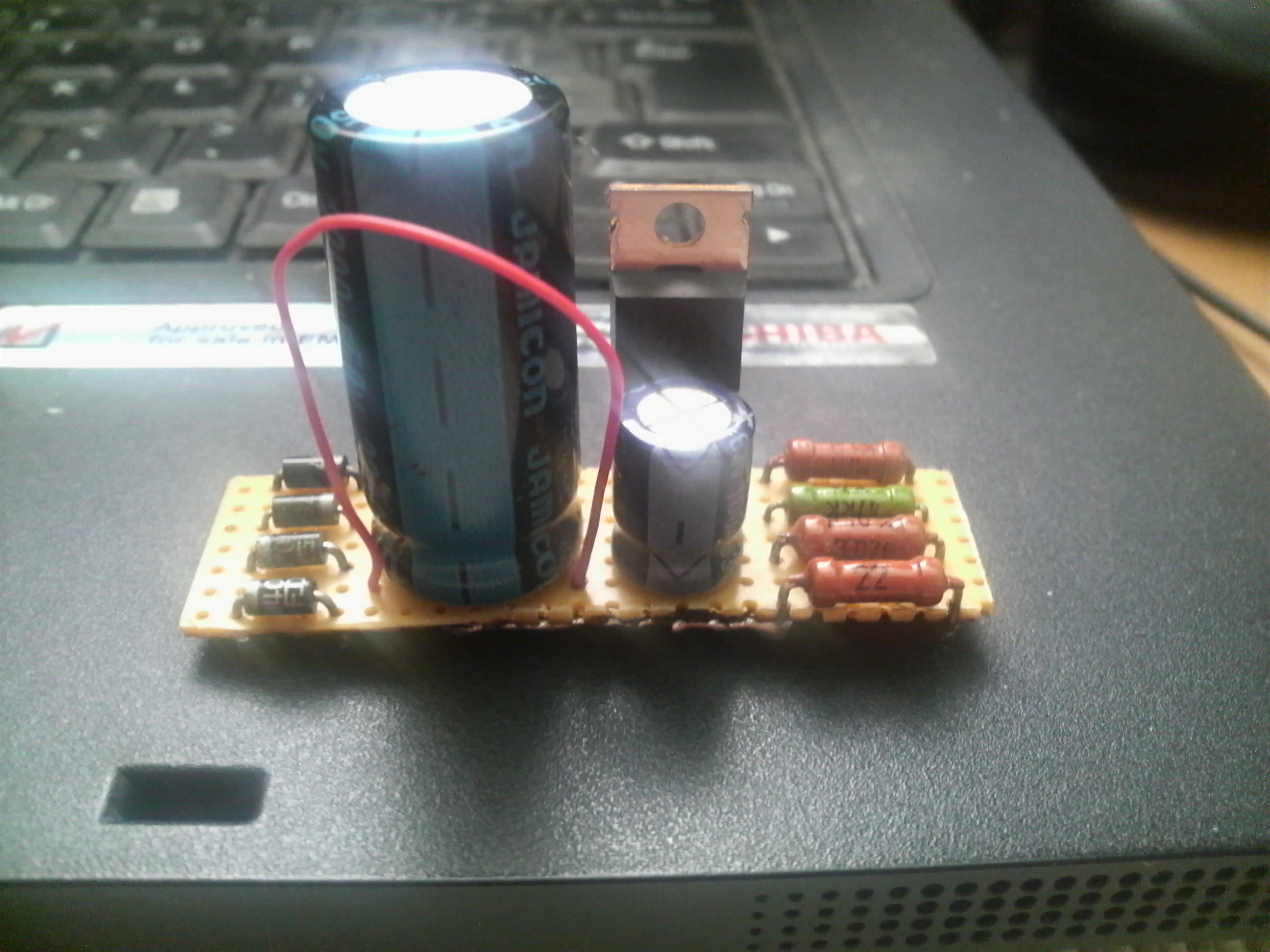
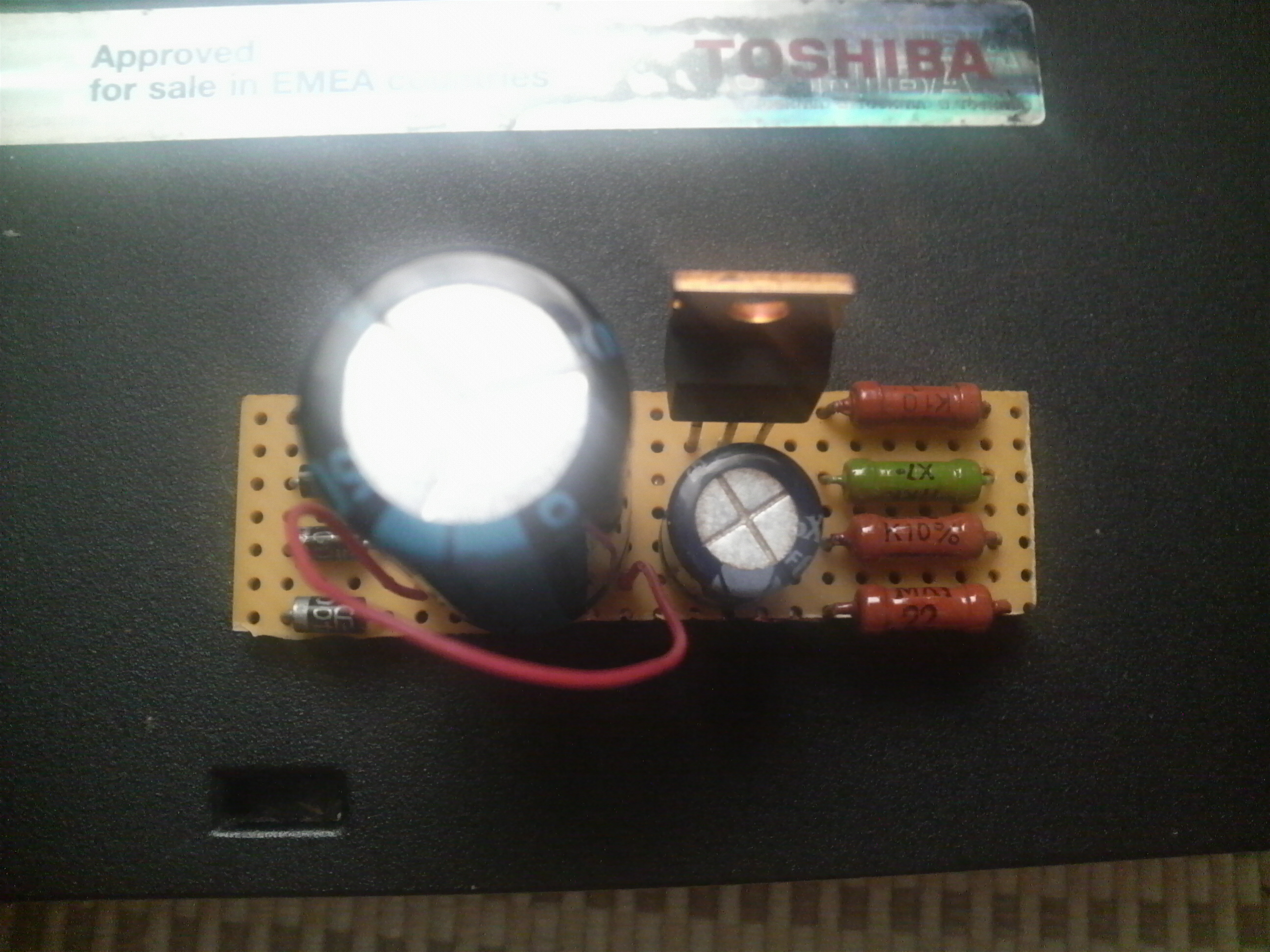
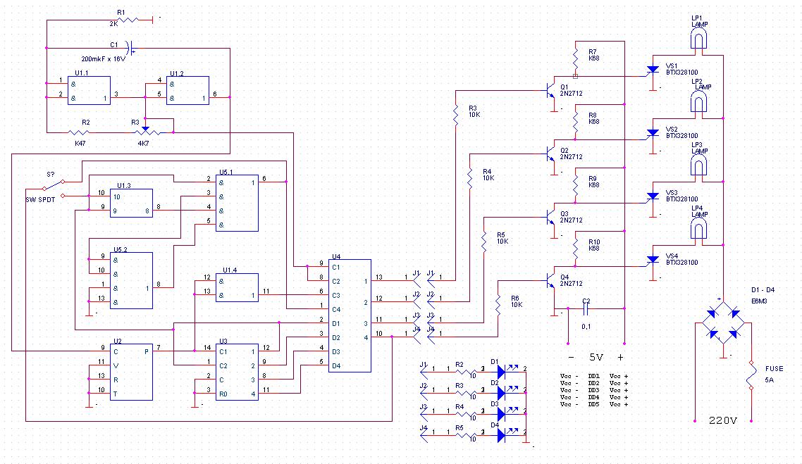
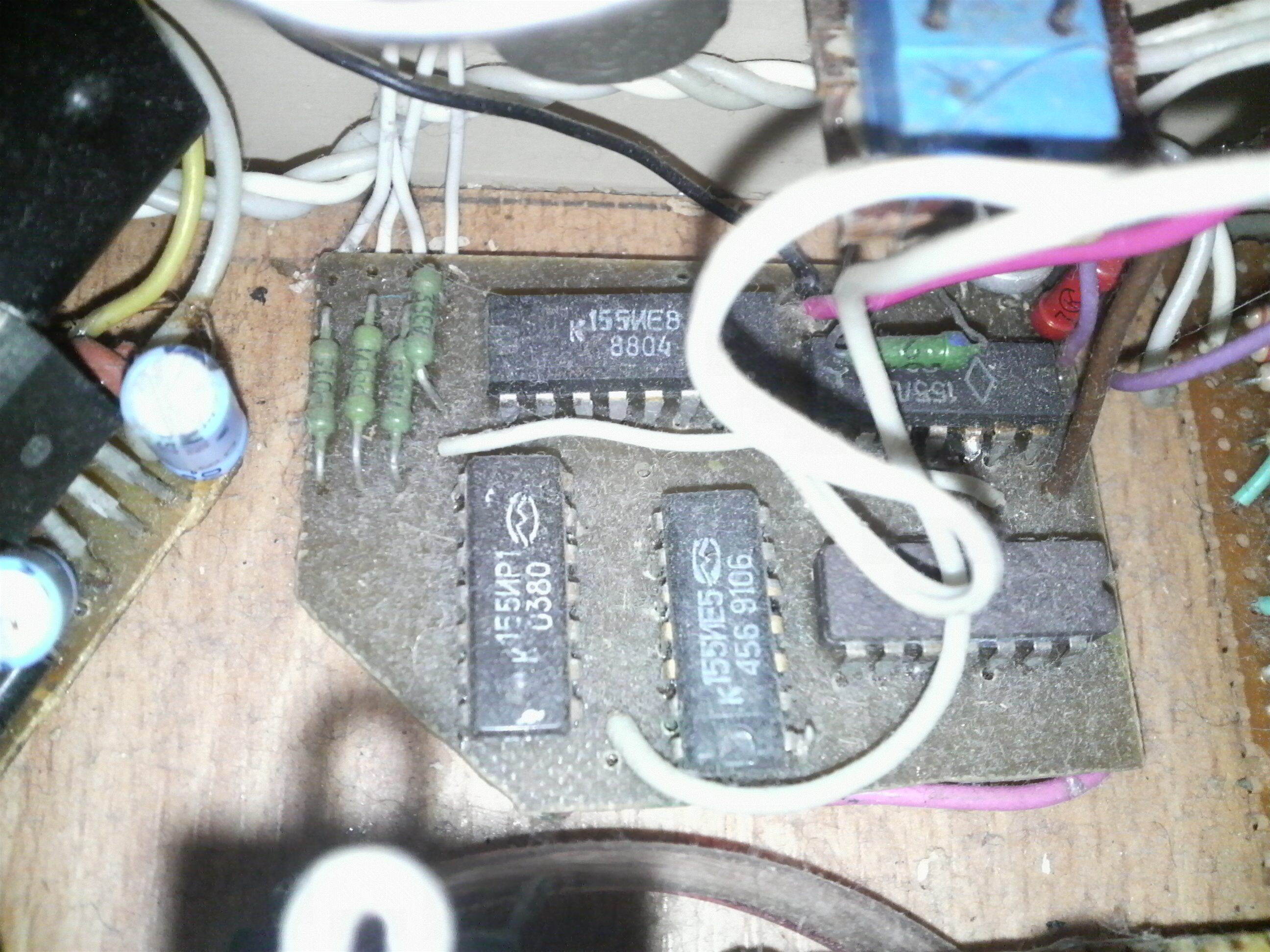
4-channel light effects machine
*****ATTENTION! HIGH VOLTAGE IS IN USE*****
As shown in the schematic diagram, you can use incandescent lamps with an additional 220 V supply. Or you can use light-emitting diodes (LEDs) without additional supply of 220V. Before the LEDs you can connect resistors to reduce the current flowing through them. Select resistors according to LEDs You will use. In my version I don,t used resistors at all before LEDs. If you will use only LEDs (not lamps with additional 220V supply), the "+" of the power supply is connected only to the microchips outputs (as shown) and the "-" to the microchips "-" and circuit's 'Earth' connections. Originally there are used Russian chips: U1 = К155ЛА3, U2 = К155ИЕ8, U3 = К155ИЕ5, U4 = К155ИР1, U5 = К155ЛР1. But you can use analog devices: К155ЛА3===SN7400N, К155ИЕ8===SN7497N, К155ИЕ5===SN7493N, К155ИР1===SN7495N, К155ЛР1===SN7450N. There are used Russian transistors KT315, thyristors - also Russian KУ202N. Bridge is from four Russian KД203B. There are showed analogue components for Russian ones in the circuit diagram. Basic datasheets of used Russian chips you can find here . Datasheets for non Russian chips you can find here . | Schematic diagram and photo of device
This ir the schematic in .pdf format |
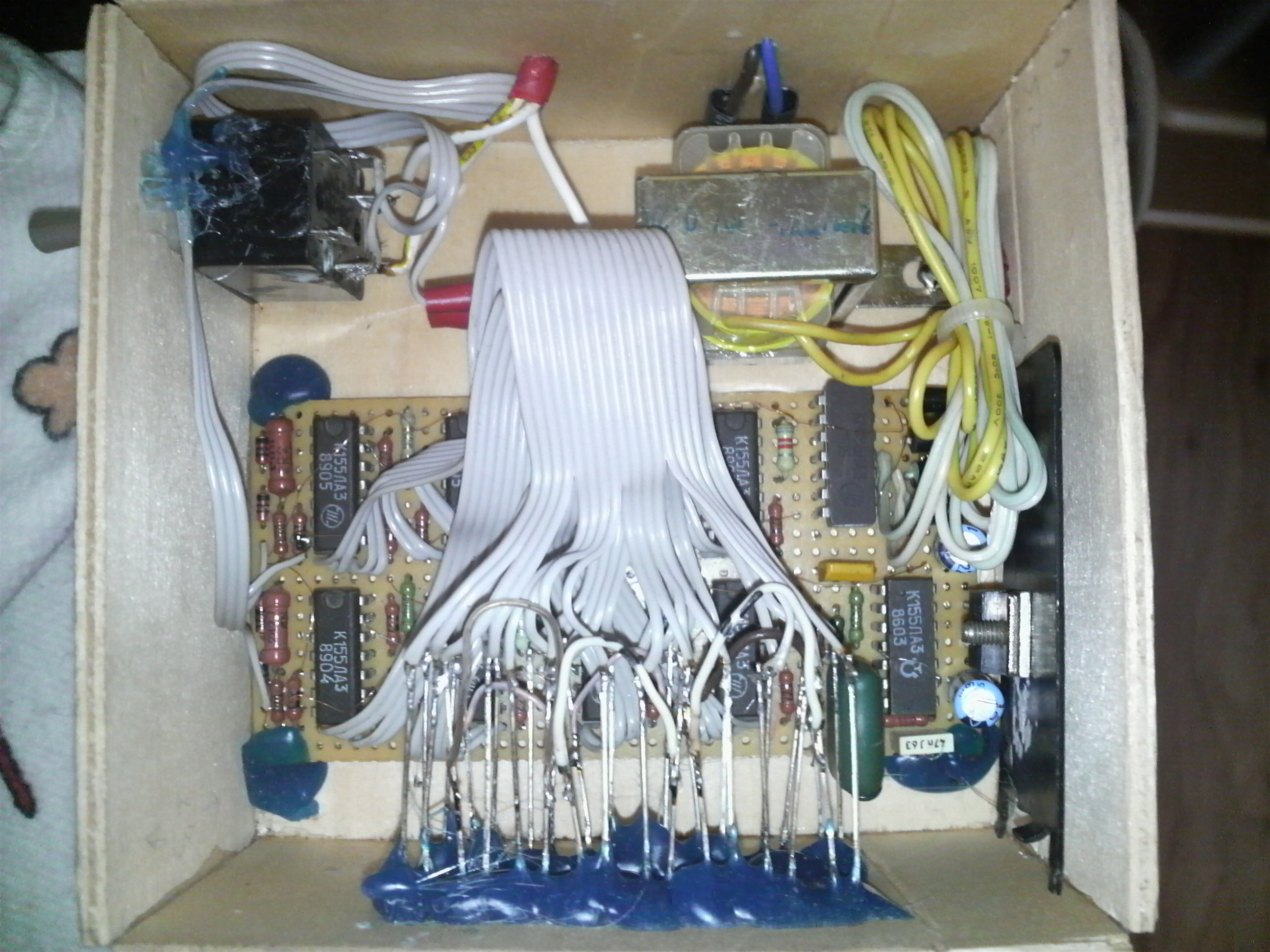
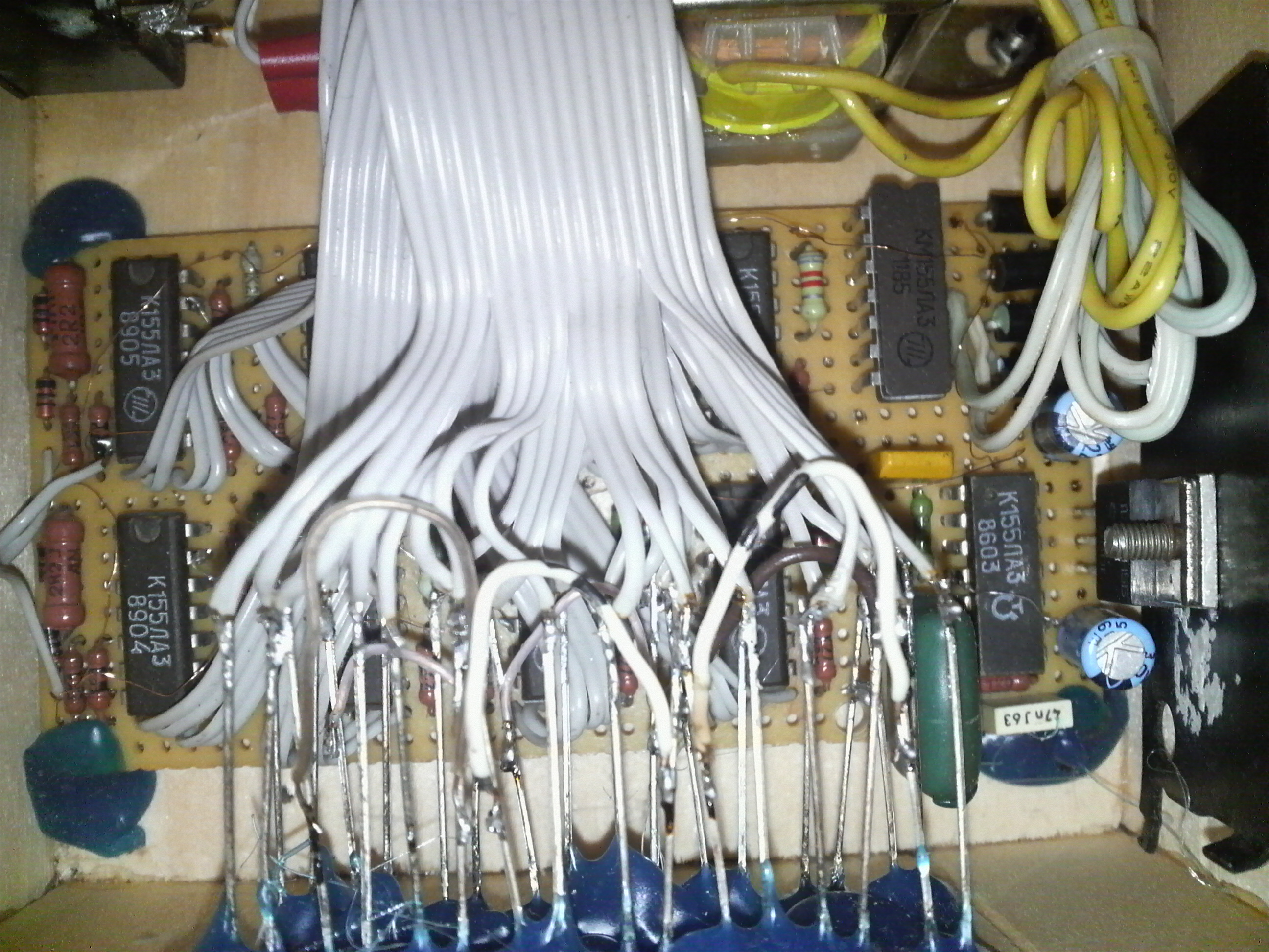
Music level indicator
You will need experimentalize when will take resistors R2, R4, R6, R8, R10, R12, R14, R16. These resistors determine the sensitivity of the device. I have made stereo indicator. For stereo use you should construct two identical parts (chanels) (defined in red rectangular in the circuit). Second part you should connect to pin 6 of the U6. Basic datasheet of used К155ЛА3 chip you can find here . Datasheet for SN7400N chip you can find here . | Device is in action... Couple of pictures...
This is the circuit in .pdf format. |